Our first “serious” Stirling engine is a “ringbom” engine. This kind of Stirling engine differs from most other configurations in that the displacer and the power piston are not connected by a crankshaft. The resulting engine is a bit magical (how does the displacer move if there is no crankshaft?!?) and noisy, but it can be self starting and will run over a reasonable range of temperatures. For more info on Stirling engines in general, check out www.stirlingengine.com.
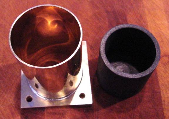
This is the 2” graphite power piston and cylinder. The cylinder is just brass tube. The graphite piston was bored out using a Forstner bit;.the cylinder was silver soldered to the base.
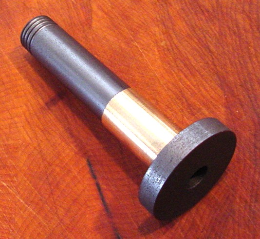
This is the displacer piston, also made of graphite. The metal sleeve is the cylinder in which the piston rides. Ringboms have two pistons and cylinders, rather than just one.
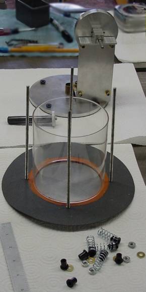
The ringbom engine, in pieces. The glass displacer cylinder is in the middle of the picture, with the displacer piston and the assembled engine top near the top of the picture. The glass cylinder is a “globe” for a Coleman lantern.
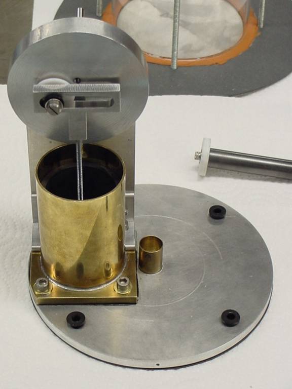
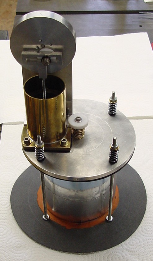
The assembled engine top, including the flywheel, power piston cylinder, displacer cylinder, and displacer piston (in the background on the right, behind the top of the engine).Note the scotch yoke used to connect the power piston to the flywheel. This approach proved to have more friction than we could afford, and we abandoned this approach after a while.
The assembled engine. Note the displacer just visible inside the glass displacer cylinder.
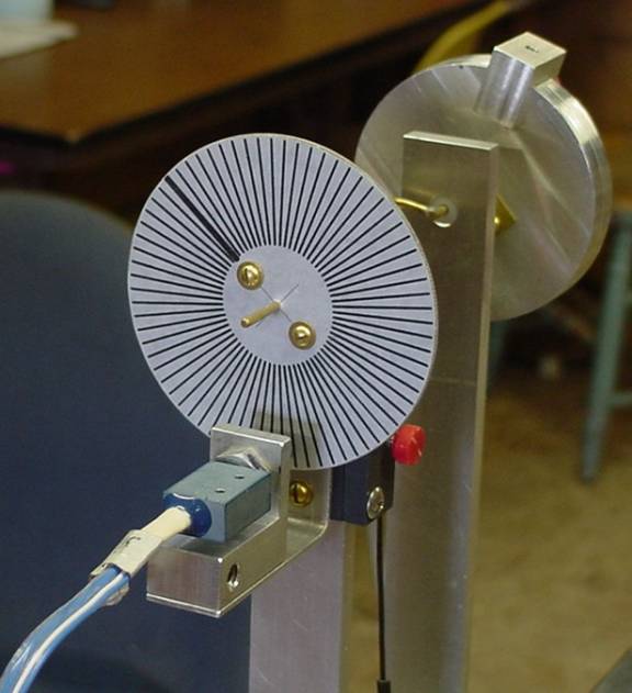
The top of the engine with a new flywheel (on the far side of the picture). There is a counter-weight attached to the flywheel. In the foreground you can see an optical sensor (at the bottom) and a wheel with a pattern of lines on it. We used the sensor and a computer program to compute the instantaneous angular velocity of the flywheel. We then moved the counter-weight around until we made the angular velocity as constant as possible (minimized the variations).
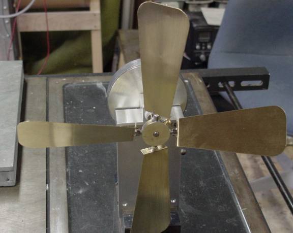
A home-brewed fan which Ralph made. It actually pushes quite a lot of air, and cools the top of the engine some 20-30 degrees F.
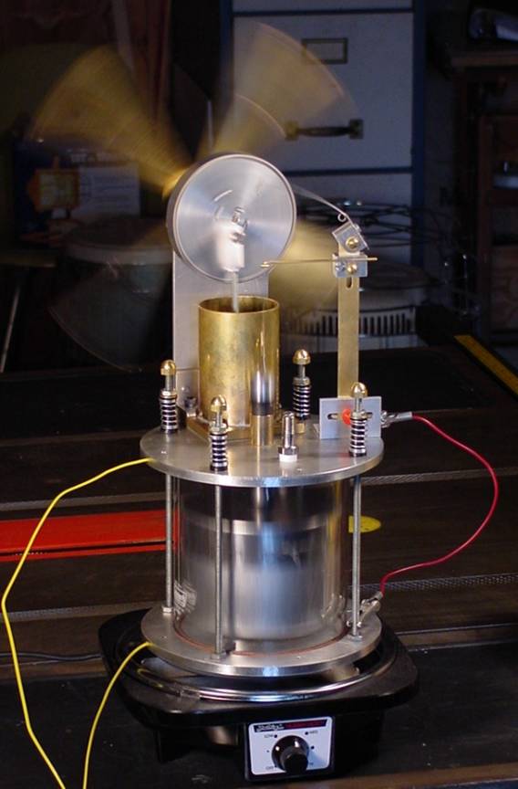
The ringbom engine with the scotch yoke replaced, the fan attached, and a spring in place to compensate for the weight of the displacer. The spring can be seen above the displacer. It looks like a fishing pole, and is attached to the aluminum blocks on top of the brass tower on the right side of the engine. Note the two yellow temperature probes. Further note that we are now using a commercial heater, rather than the tin can and light bulb. The displacer is made out of aluminum, and is sealed with aluminum tape. The tape adhesive failed after a while, as did the fishing rod spring.
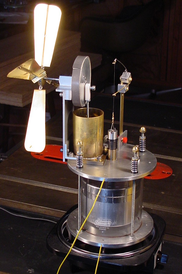
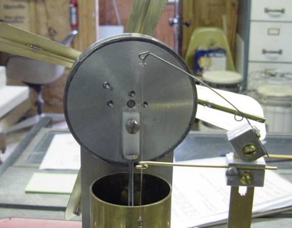
The same engine, at work. The fishing rod spring can be seen at the top of the brass tower, on the right, with a small loop at its base. The horizontal brass wire is used to center the string which attaches the spring to the displacer.
A close-up of the spring assembly and guide. The numerous holes on the flywheel allow us to set the engine up with a variety of different power piston throws.
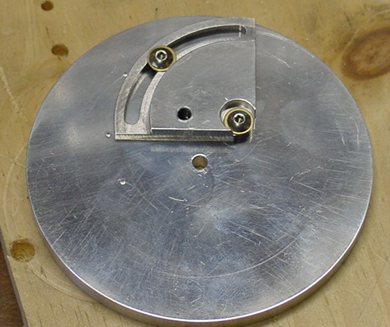
Ralph’s latest idea, a fixture to allow infinitely adjustable power piston throws.
The latest version of this engine, showing the displacer spring adjustment fixture. Different springs alter the engine performance, as does adjusting the height of the spring. Adjusting the rest position of the displacer effects the temperature at which it starts to operate and the temperature at which it starts to over-run.
